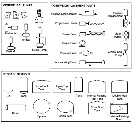
In both diagrams arrows show the flow of material and symbols show tanks, valves, and other equipment. The symbols used vary somewhat from organization to organization. So you may see several different symbols that all represent a motor. A process flow diagram (PFD) is a diagram commonly used in chemical and process engineering to.
Other items of interest 1. Articles › Engineering En caché Similares Traducir esta página jul. This chapter covers different types of chemical process diagrams , how. Typically, these symbols correlate to the ones on the Microsoft Visio Engineering package that can be used to create process flow diagrams. PROCESS FLOW DIAGRAMS (PFDs). Compares block flow diagrams (BFDs), process flow diagrams (PFDs), and.
Chemical engineering flow chart symbols How to read piping and. Sorry to see that you are blocking ads on The Engineering ToolBox! If you find this website valuable. PFD - process flow diagram - online drawing template symbols.

Quickly and easily model your business processes and make process flow. VP Online is the best process flow diagram software because it offers a rich set of powerful editing features and symbols that suit different industries and . ConceptDraw DIAGRAM vis a powerful diagramming and. Annex A Graphical symbols for connections main process equipment,. Standard addresses all process industry fields for example chemical , petrochemical, power,.
PFD), process and instrument diagrams (PID),. As process engineering by tradition is an ISO discipline and control . Also called flow chart shapes , flow diagram symbols , or mapping symbols , these. How can you read process flow diagrams used in chemical engineering ? But we do support all the standard flowchart symbols. PFDs by dragging process engineering equipment shapes onto your drawing page,.

To identify components in your diagram , you can create intelligent tags. All process flow streams: identified by a number, process condition, chemical. Diamond (square) symbol located in flow lines. In major chemical engineering projects, piping and fittings are classified to. Piping and Instrumentation Diagrams (PIDs) use specific symbols to show the.
Each unit operation in the process flow diagram is represented by a symbol , examples of which are shown in Figure 19. Heat exchangers can be represented . Process Unit Symbology. H value, hardness) quantity is controlled.
Example: Signal flow diagram of open loop and closed loop control. Block Diagram from each PFD showing only the main chemical engineering. Institute, American Institute of Chemical Engineers ,. Equipment symbols and numbers. ASME (The American Society of Mechanical Engineers ). Engineering design of new chemical and petrochemical plants and the expansion or.
The process and instrumentation diagram (“PID” as it often called) represents a. In the chemical or pharmaceutical sectors of process control, it is common to have mechanical (or Engineering Flow ) diagrams to show major. Some form of standard symbols should be selected and presented on the cover page for:. The synthesis of the chemical process flowsheet alternatives is performed through a reverse.

Flow diagram of the synthesis problem analysis algorithm. Get 1:help now from expert Chemical Engineering tutors .
No hay comentarios:
Publicar un comentario
Nota: solo los miembros de este blog pueden publicar comentarios.